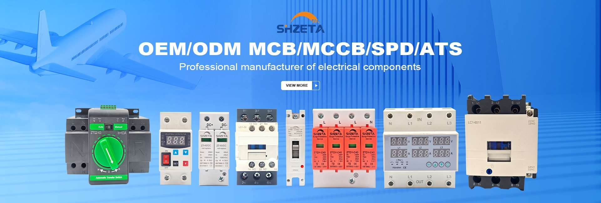

Zhejiang Graybar Electric low-voltage surge protective devices and switchgear assembly lines
Surge Protective Device factory manufacturing and testing warehouse in Liushi Wenzhou

Multilingual Engineering Support

Our power engineering team assists procurement managers across 16 languages with direct technical compliance review.

  • GermanDeutsch
  • PortuguesePortuguês
  • SpanishEspañol
  • FrenchFrançais
  • ItalianItaliano
  • RussianРусский
  • Korean한국어
  • Japanese日本語
  • Arabicالعربية
  • Thaiภาษาไทย
  • VietnameseTiếng Việt
  • TurkishTürkçe
  • DutchNederlands
  • IndonesianIndonesia
  • Hebrewעברית
  • Hindiहिंदी
Direct Factory Engineering Guide

How Global Engineers and EPC Contractors Source Surge Protective Devices (SPD) to IEC 61643-11 Standards

In an era dominated by renewable grid integration, rapid EV charging infrastructure, automated industrial controllers, and intense climatic lightning exposure, selecting the correct Surge Protective Device (SPD) has evolved from a basic compliance check into a mission-critical asset reliability strategy. Zhejiang Graybar Electric Co., Ltd. manufactures heavy-duty, DIN-rail low-voltage SPDs engineered to safeguard sensitive commercial, industrial, and residential electronics against devastating direct lightning strikes and high-energy inductive switching transients.

Type 1, 2 & 3 Full Spectrum AC & DC Photovoltaic SPD Fast Nanosecond Response IEC 61643-11 Compliant
< 25 ns High-speed clamping response time across all MOV configurations
50 kA – 100 kA Maximum discharge capacity (Imax) for industrial distribution panels
5 pcs Ultra-low starting MOQ for standard DIN-rail AC/DC SPD prototypes
100% Factory QC Varistor voltage (U1mA) and leakage current verification before shipment
Engineered Recommendations

Featured Surge Protective Device Lineup

From main service entry points to localized terminal instrumentation, select modular, pluggable cartridge SPDs designed for maximum operational uptime and seamless integration.

Flagship Series · Heavy-Duty Transient Arresters

Modular AC & DC Surge Protection Devices

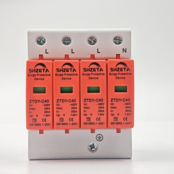
Manufactured in our authenticated Liushi production facility, our Surge Protective Devices utilize premium zinc-oxide Metal Oxide Varistors (MOV) and high-energy Gas Discharge Tubes (GDT). Each pole features an internal dual-action thermal disconnector, visual mechanical status indicator (Green=Normal, Red=Fault), and optional remote signaling contacts for centralized SCADA or building management alert systems.

1P, 2P, 3P, 4P, 3P+N Up to 1000V DC / 440V AC Class I & Class II DIN-Rail 35mm
Zhejiang Graybar Electric surge protective device manufacturing assembly
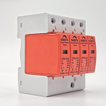
3 Phase Surge Protection Device Type 2 for industrial distribution

3 Phase Surge Protection Device (Type 2 / Class II)

Engineered for four-wire 400V AC three-phase industrial panels and commercial main distribution boards (MDB). Protects automation systems against switching surges.

  • Nominal Voltage (Un)230V / 400V AC (50/60Hz)
  • Max Operating Voltage (Uc)275V / 385V / 440V AC
  • Nominal Discharge (In)20 kA (8/20 μs)
  • Max Discharge (Imax)40 kA – 65 kA (8/20 μs)
  • Voltage Protection Level (Up)≤ 1.5 kV – 1.8 kV
  • Configuration3P+N / 4P Pluggable Cartridge
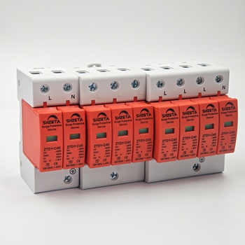
Single phase AC surge protective device SPD for sub-panels

Single Phase AC Surge Protector (Type 2 / Type 3)

Tailored for residential consumer units, telecom power supplies, single-phase heat pumps, and sensitive lighting branch boards exposed to inductive surges.

  • Nominal Voltage (Un)220V / 230V AC
  • Max Operating Voltage (Uc)275V / 320V AC
  • Nominal Discharge (In)10 kA – 20 kA (8/20 μs)
  • Max Discharge (Imax)20 kA – 40 kA (8/20 μs)
  • Response Time (tA)< 25 nanoseconds
  • Configuration1P+N (MOV + GDT Zero Leakage)
Heavy duty surge protector arrester for industrial service entry

Industrial Type 1+2 Combined Surge Arrester

Designed for service entry facilities equipped with external lightning protection rods. Features robust spark-gap and heavy-duty MOV hybrid architecture.

  • Design StandardIEC 61643-11 Class I+II
  • Impulse Current (Iimp)12.5 kA – 25 kA (10/350 μs)
  • Nominal Discharge (In)25 kA – 50 kA (8/20 μs)
  • Short Circuit Rating (Isccr)25 kA / 50 kA without backup
  • Housing MaterialUL94-V0 Thermoplastic
  • Remote SignallingForm C dry contact included
Engineering Reference

Surge Protective Device Selection Matrix by Earthing System

Correct SPD pole count and Uc configuration depend directly on the earthing topology (TN-C, TN-S, TT, or IT) and installation location.

Grid Earthing System Network Type Recommended Configuration Typical Max Continuous Voltage (Uc) Connection Mode & Application Note
TN-C System Combined neutral and protective earth (PEN conductor) 3P (3 Poles) 275V – 385V AC (L-PEN) Varistors connected between each phase and PEN. Economical 3-module installation for commercial industrial entrances.
TN-S System Separate neutral (N) and protective earth (PE) throughout 4P or 3P+N 275V AC (L-N), 255V AC (N-PE) Protects phase-to-neutral and neutral-to-earth independently. Essential for computerized clean environments.
TT System Neutral earthed at source; load frames earthed locally 3P+N ("1+1" or "3+1" mode) 275V AC (L-N), 255V AC (N-PE via high-energy GDT) Mandatory "3+1" circuit: Prevents short-circuit fault current from creating lethal touch voltages on local PE rods if a varistor fails.
IT System Isolated or impedance-grounded neutral system 3P or 4P High Uc 440V – 690V AC Must withstand line-to-line phase voltage during a first ground fault without tripping or thermal degradation.
Photovoltaic DC Floating or grounded DC solar string circuits 2P / 3P Y-Configuration 600V, 1000V, 1500V DC Three-branch varistor network with isolated middle tap to prevent destructive ground short arcs during failure.

* Engineering reminder: To ensure effective protection under IEC 60364-5-53, total lead length (A+B) connecting conductors from busbar to SPD and from SPD to earth bar should not exceed 0.5 meters (50 cm) to minimize inductive voltage drop ($L \cdot di/dt$).

Cascaded Protection Principles

How to Coordinate Upstream Breakers & Cascaded SPDs

A single SPD cannot protect an entire installation. Effective transient defense requires cascaded Class I, II, and III protection coordinated with upstream overcurrent devices.

1. Energy Coordination Between Cascade Stages

When a building receives a lightning impulse, the heavy-energy Type 1 SPD at the main switchboard must discharge the bulk of the 10/350 μs impulse current. Downstream Type 2 SPDs in floor sub-panels clamp the residual voltage, while Type 3 SPDs provide fine point-of-use protection.

To prevent downstream Type 2 SPDs from prematurely triggering and bearing the full strike before the upstream Type 1 reacts, proper decoupling must exist. This is achieved through either:

  • Physical Cable Decoupling: At least 10 meters of cable inductance between Class I and Class II devices.
  • Engineered Triggering: Using spark-gap devices with electronic triggering or coordinated MOV voltage thresholds that ensure upstream energy dissipation occurs first.

2. Upstream Overcurrent Protection (Backup Fuse / MCB)

An SPD is an open circuit under normal conditions. When it diverts a surge, it momentarily exhibits low impedance. If hit by a surge exceeding its rated maximum capacity ($I_{max}$), the varistor may fail into a short-circuit state. While Zhejiang Graybar Electric Co., Ltd. units feature internal thermal disconnections, external dedicated backup overcurrent protection (such as a coordinated 32A–63A gG fuse or a high-breaking-capacity MCB) is mandatory to isolate short-circuit fault current safely.

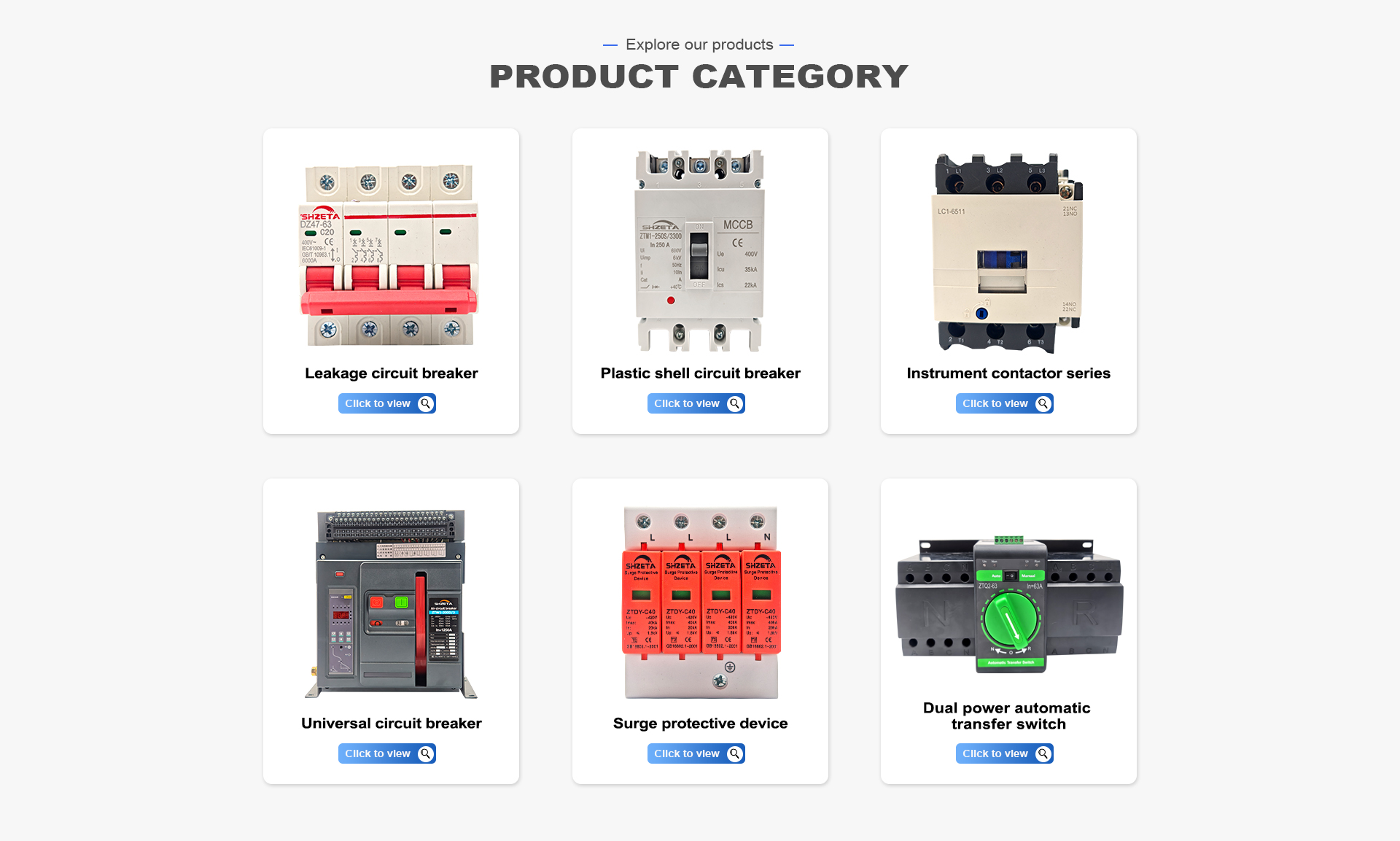
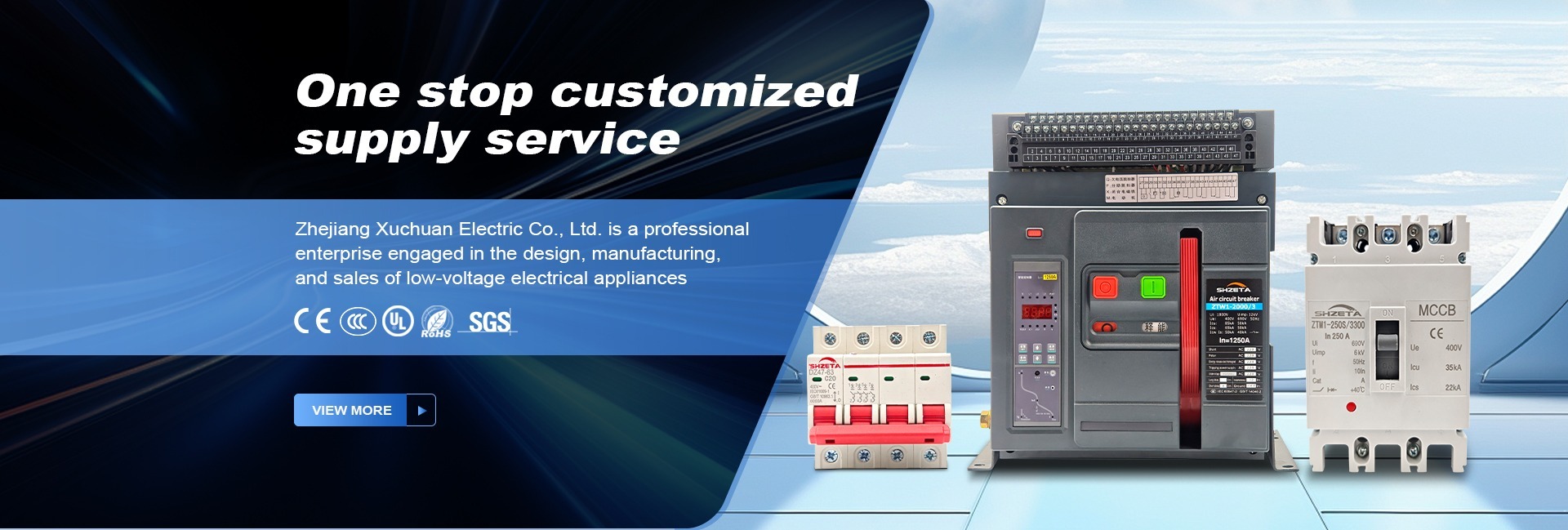
Comprehensive circuit protection lineup: MCB, MCCB, ACB and SPD coordination
Integrated circuit protection architecture: Seamless coordination between upstream ACB/MCCB breakers and downstream Surge Protective Devices.
Manufacturing Authority

Why Global Electrical Sourcing Heads Choose Zhejiang Graybar Electric

Located in Liushi, Wenzhou—China's low-voltage electrical capital—we combine factory direct pricing, deep supply chain integration, and rigorous testing protocols.

Liushi Component Ecosystem

  • Direct geographical access to specialized zinc-oxide varistor disk fabricators and high-purity copper busbar suppliers
  • Rapid raw material turnaround and reduced component lead times
  • Customized housing designs, color molds, and specialized DIN configurations produced on rapid schedules

Rigorous In-House Testing

  • 100% verification of varistor breakdown voltage (U1mA) and leakage current (IμA) on dedicated automated test benches
  • Thermal disconnector trip calibration under high-current thermal stress simulation
  • Impulse current discharge tests performed to verify clamping voltage curves before batch release

Agile Export Logistics & MOQs

  • Starting MOQ of only 5 pieces for standard AC/DC Surge Protective Devices, enabling rapid pilot project approval
  • Consolidated shipping with complementary MCBs, MCCBs, and ACBs from one unified container manifest
  • Robust shock-absorbing export packaging engineered for rough intermodal ocean freight and air courier transport

OEM / ODM Engineering Customization

  • Full private-label laser marking, custom part numbering, and tailored retail/contractor packaging
  • Engineering support for single-line diagram (SLD) reviews and cascaded selective protection schemes
  • Comprehensive export documentation: Certificates of Origin, commercial compliance sheets, and test curves
Standardization & Quality Assured

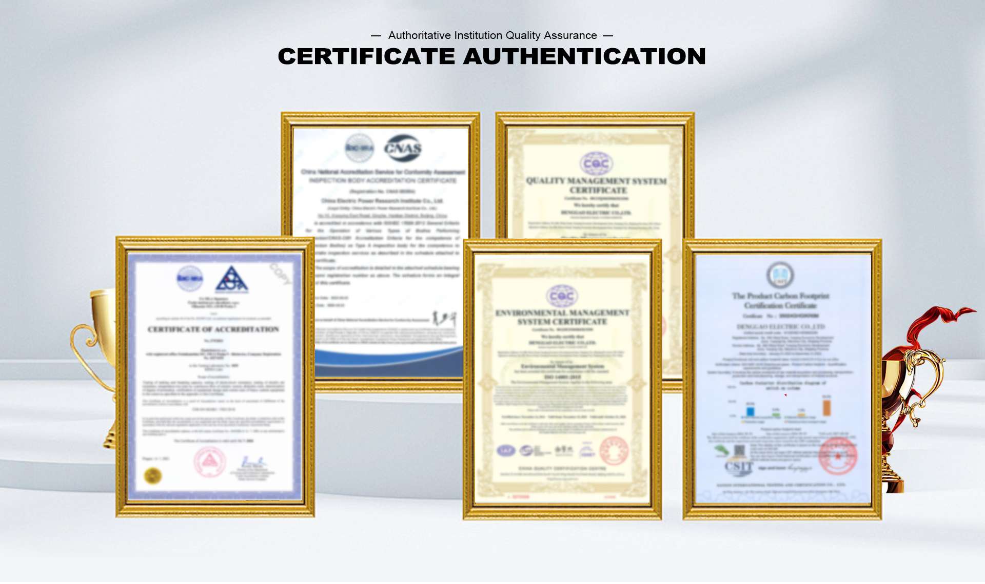
Certified Testing & IEC Compliance Standards

Our Surge Protective Devices are engineered and evaluated according to internationally recognized testing methods.

IEC 61643-11

Low-voltage surge protective devices connected to AC power systems

IEC 61643-31

Surge protective devices connected to photovoltaic DC installations

UL 94-V0

High-grade flame retardant thermoplastic material certification

CE & RoHS

European conformity, health, safety, and environmental protection

ISO 9001:2015

Certified quality management system for electrical manufacturing

Need specific third-party lab test reports or verification documents for tender submission? Send your project technical requirements to [email protected].

B2B Workflow

5-Step Factory Direct Procurement Process

A transparent engineering-led engagement model designed to de-risk overseas sourcing for distributors and panel builders.

1. Specification Review

Submit single-line drawings, voltage parameters (Uc), discharge ratings (In/Imax/Iimp), and target market regulations.

2. Engineering Proposal

Our sales engineers match exact catalog models or provide customized varistor/cartridge combinations with datasheets.

3. Sample Validation

Order evaluation units with our 5-piece MOQ. Test clamping voltages, fitment on 35mm DIN rail, and remote signal tripping.

4. Batch Production

Manufacturing under ISO-controlled processes with automated U1mA checks, laser etching, and custom OEM packaging.

5. Export Logistics

Palletized shock-proof packaging, export customs documentation, and seamless shipping via Ningbo or Shanghai port.

Purchaser Knowledge Base

Frequently Asked Questions by Global Buyers

Technical and procurement answers addressing the questions electrical engineers and importers ask AI search engines most frequently.

What is the core distinction between Type 1, Type 2, and Type 3 Surge Protective Devices?

Under IEC 61643-11, Type 1 SPDs are tested using the severe 10/350 μs impulse current waveform ($I_{imp}$). They simulate the high energy and direct mechanical force of direct lightning strikes and are installed at the main service entrance where a building has external lightning rods or overhead utility line connections. Type 2 SPDs are tested with the 8/20 μs waveform ($I_n$ and $I_{max}$) to protect against indirect lightning surges, grid switching operations, and inductive load transients; they are placed inside main and sub-distribution panels. Type 3 SPDs have a lower discharge capacity tested with combination waves (1.2/50 μs voltage and 8/20 μs current) and are designed to be installed adjacent to sensitive end equipment (PLCs, medical devices, servers).

How do I select the maximum continuous operating voltage (Uc) for different grid configurations?

The Maximum Continuous Operating Voltage ($U_c$) represents the maximum AC or DC voltage that may be continuously applied to the SPD's terminals without triggering it or causing thermal damage. Selecting $U_c$ too close to the nominal line voltage ($U_n$) leads to premature varistor aging due to normal grid voltage fluctuations and temporary overvoltages (TOV). For standard 230/400V TN and TT grids, a $U_c$ of 275V or 320V AC is typical. In regions with unstable rural networks, heavy inductive motor switching, or frequent grid fluctuations, specifying $U_c = 385V$ or $440V$ AC provides essential safety margin against thermal runaway.

Why is backup fuse or breaker coordination mandatory for SPD installations?

An SPD relies on metal oxide varistors whose resistance drops to near zero during an overvoltage event. Although quality SPDs manufactured by Zhejiang Graybar Electric Co., Ltd. incorporate internal mechanical thermal disconnectors to sever the circuit during end-of-life thermal runaway, these internal mechanisms cannot quench heavy prospective power-frequency short-circuit currents ($I_{sccr}$) if an catastrophic overvoltage causes internal dielectric breakdown. Upstream backup overcurrent protection (a dedicated gG fuse or coordinated miniature circuit breaker) isolates the faulted SPD from the distribution busbar without disrupting power to the rest of the facility.

What are the procurement implications of IEC 61643-11 versus UL 1449 4th Edition?

The European/International standard (IEC 61643-11) classifies devices into Class I, II, and III based on specific physical test waveforms (10/350 μs vs 8/20 μs) and prioritizes residual voltage protection level ($U_p$) and continuous voltage ($U_c$). The North American standard (UL 1449) designates SPDs as Type 1, 2, 3, 4, or 5 based strictly on where the device is located in the electrical distribution tree (e.g., line side vs load side of main service disconnect) and evaluates Voltage Protection Rating (VPR) and Nominal Discharge Current ($I_n$). Importers must clarify whether their local market or project specifications mandate CE/CB reports (IEC) or UL listings.

How do environmental harshness and harmonics affect SPD operational lifespans?

High operating temperatures inside unventilated outdoor panels accelerate varistor leakage current drift, reducing MOV operational life. Simultaneously, circuits downstream of high-frequency Variable Frequency Drives (VFDs) and non-linear power supplies carry repetitive voltage spikes and high harmonic contents. These small, repetitive micro-surges chip away at the ceramic varistor micro-structure over time. In harsh, harmonically rich environments, Zhejiang Graybar Electric Co., Ltd. recommends selecting higher $U_c$ thresholds and hybrid MOV+GDT zero-leakage topologies to avoid premature aging.

What is the minimum order quantity (MOQ) and production lead time for custom SPDs?

To support project prototyping, testing, and small contractor orders, our standard catalog Surge Protective Devices have a low MOQ of just 5 pieces per model. For customized private labeling, specialized voltage ratings ($U_c$), OEM laser marking, and customized packaging, the typical MOQ begins at 100 to 500 units. Standard sample orders ship within 3 to 7 business days, while volume commercial container orders have a production cycle of approximately 15 to 25 days from technical confirmation.

Need Factory-Direct Surge Protective Devices?

Send your bill of materials, single-line diagrams, or tender specifications directly to [email protected]. An experienced technical sales engineer will provide a comprehensive quotation and compliance package.

Contact Us Factory Contact Details