Standard & Custom OEM Power Switching Components
Direct from our manufacturing facility in Liushi, Wenzhou—China's capital of low-voltage electrical apparatus. Certified to international endurance benchmarks with configurable coil voltages, terminal geometries, and auxiliary combinations.
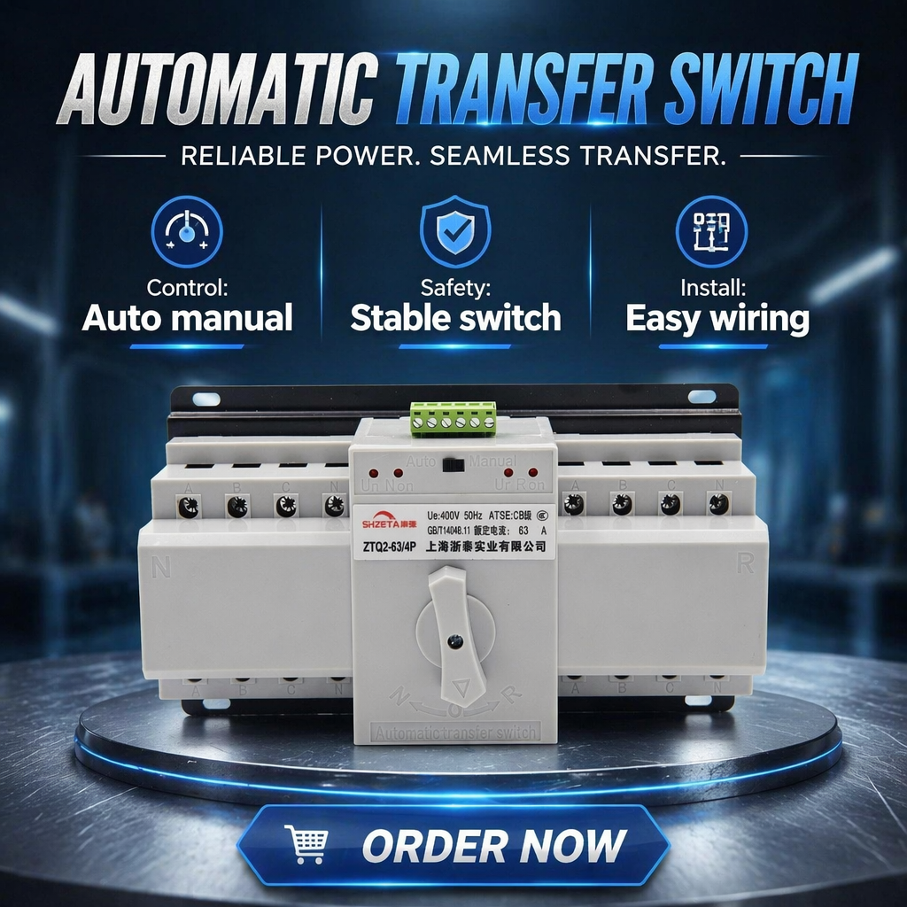
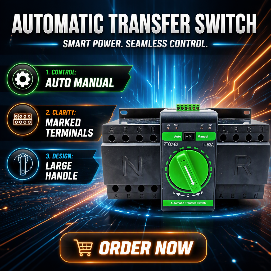
4P 63A Manual Changeover Switch Reliable Dual Power Transfer Integrated Circuit Breaker Type ATS
- Pole Architecture: 4 Pole (3P+N)
- Thermal Current (Ith): 63 Amperes
- Rated Operational Voltage: AC 400V 50/60Hz
- Mechanical Interlock: Fail-Safe Physical Bar
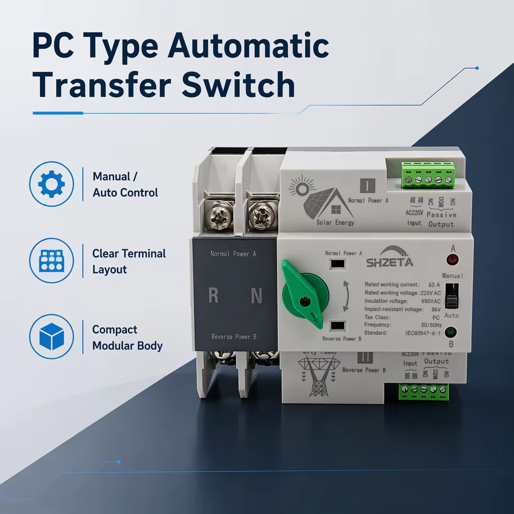
PC Type Automatic Transfer Switch 220V AC Manual Auto Control Modular Changeover Device for Solar Power
- Utilization Category: PC Class (No-Arc Break)
- Control Voltage: 220V AC Modular
- Switching Speed: < 50ms Seamless
- Application Target: PV Inverter / Grid Sync
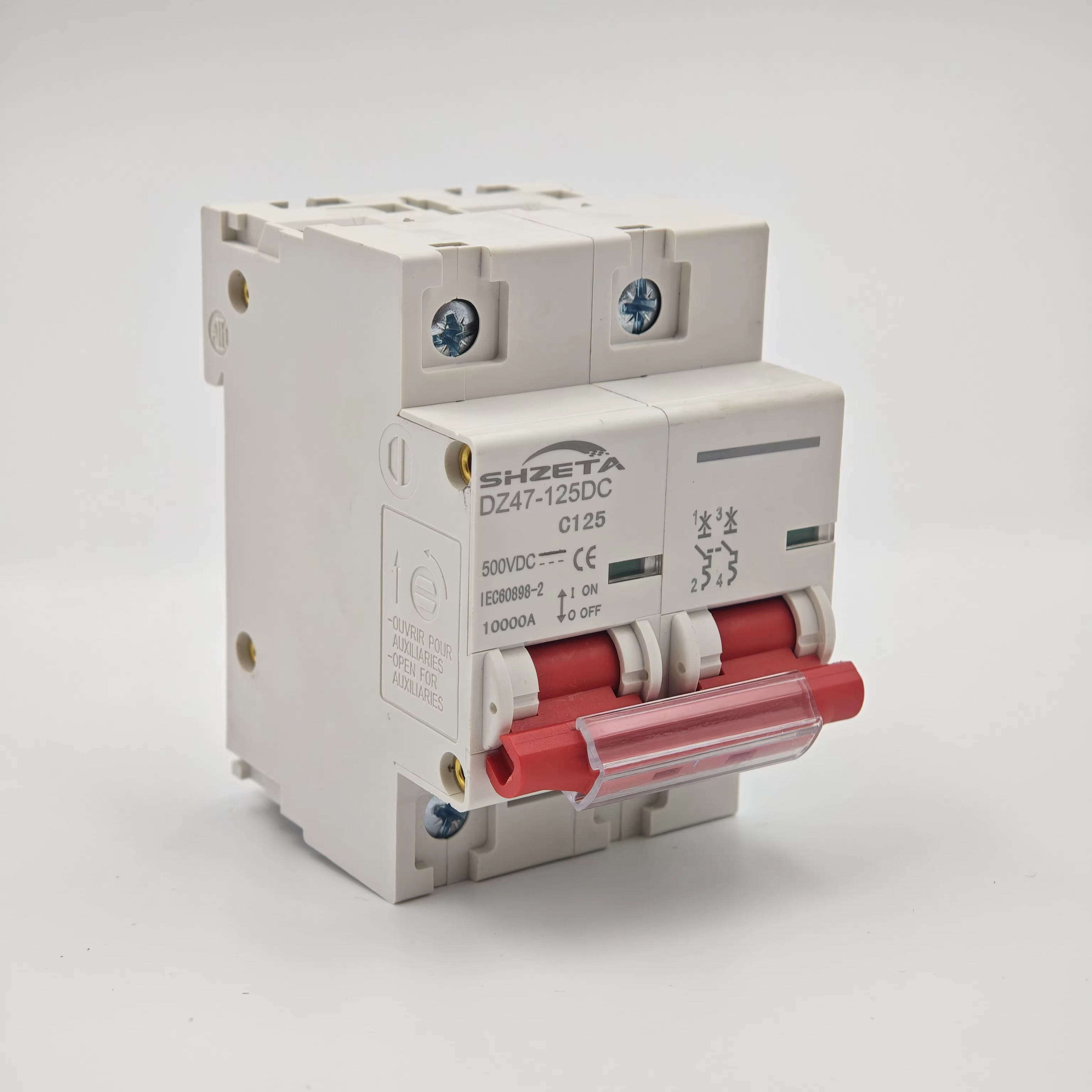
2P 80A 100A 125A DC MCB 500V Circuit Breaker Main Switch C Curve Photovoltaic
- Rated DC Voltage: 500V DC Series
- Frame Current Range: 80A / 100A / 125A
- Trip Characteristic: C-Curve Magnetic
- Arc Quenching: Magnetic Blowout Plates
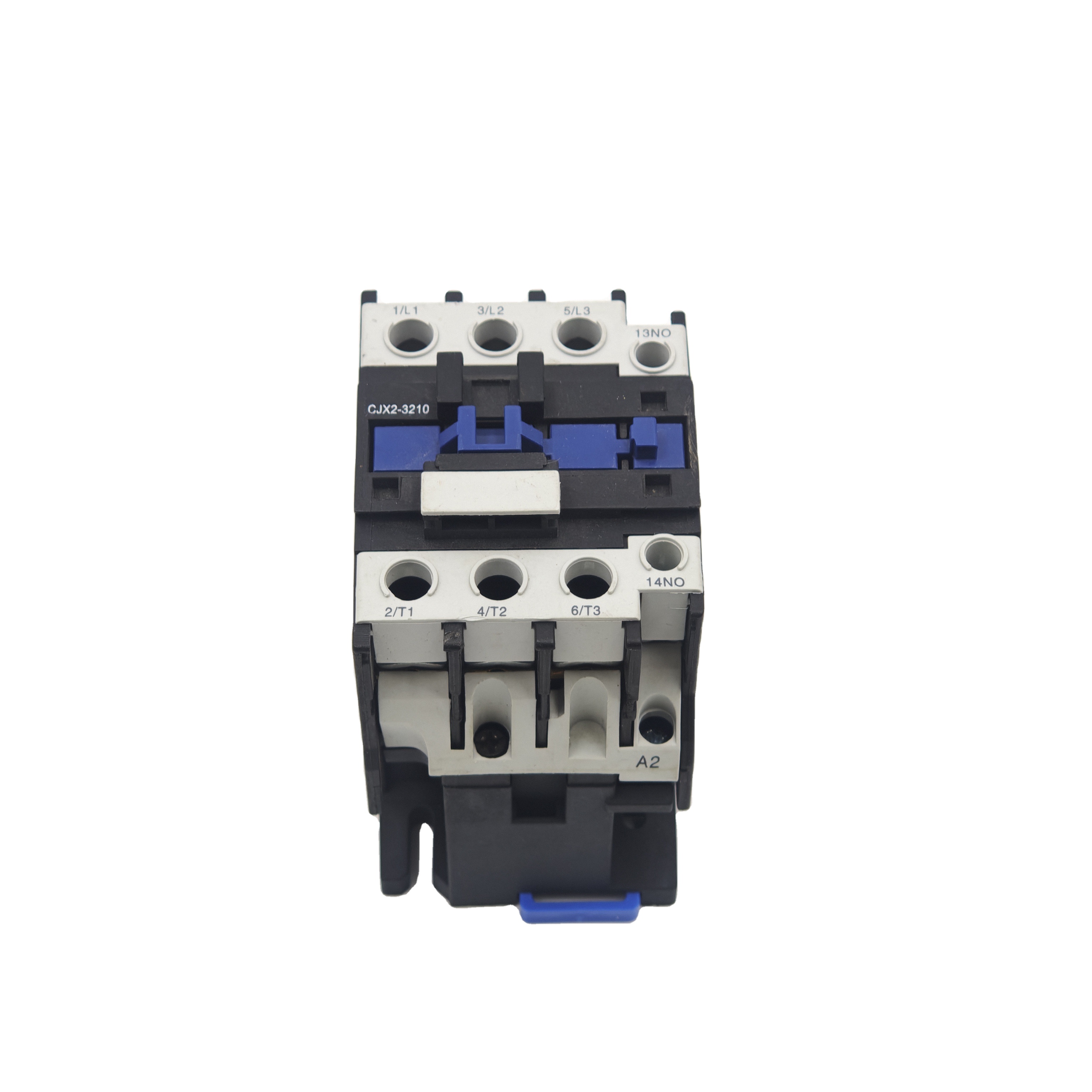
CJX2-1210 3 Phase Magnetic Contactor 220V Coil 50Hz 380V 12A AC Motor Control DIN Rail Industrial Automation
- Rated Operating Current: 12A (AC-3 @ 380V)
- Auxiliary Contacts: 1NO Built-In
- Control Coil: 220V AC 50/60Hz
- Mounting Style: 35mm DIN Rail / Screw
Customizable 2-Pole 4P Single/Three Phase Manual Conversion ATS 10kA Breaking Capacity 125A Frame Current
- Breaking Capacity: 10kA (Icu @ 400V)
- Frame Current (In): Up to 125A Selectable
- Phase Config: 2P Single / 4P Three
- Endurance Rating: 8,500 Cycles Electrical
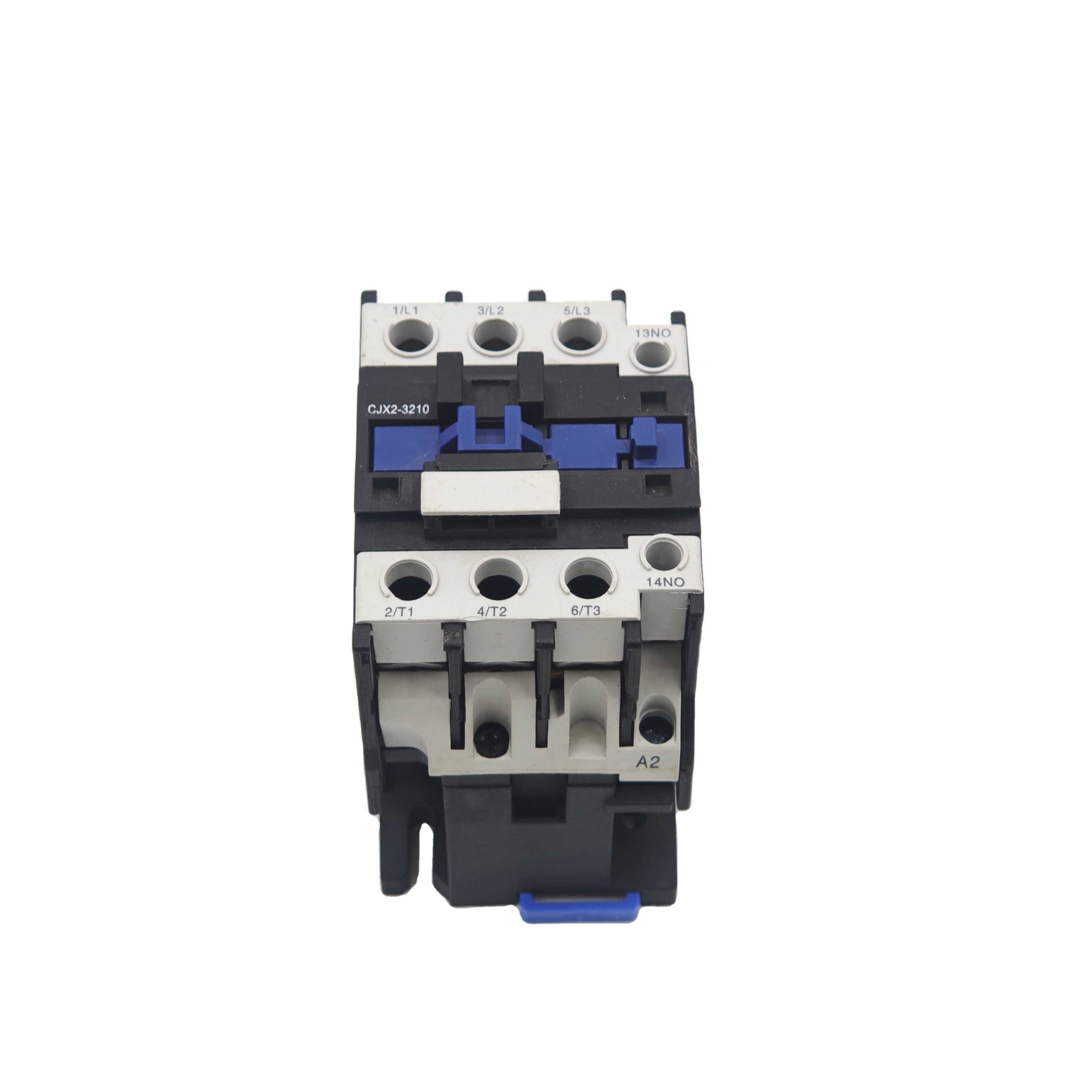
CJX2-1210 Magnetic Electric Contactor AC Three-Phase Surface-Mounted 220V/380V Industrial Spec
- Contact Composition: 85% AgSnO2 Alloy
- Insulation Voltage (Ui): 690V AC
- Operating Frequency: 1,200 Ops / Hour
- Standard Compliance: IEC/EN 60947-4-1
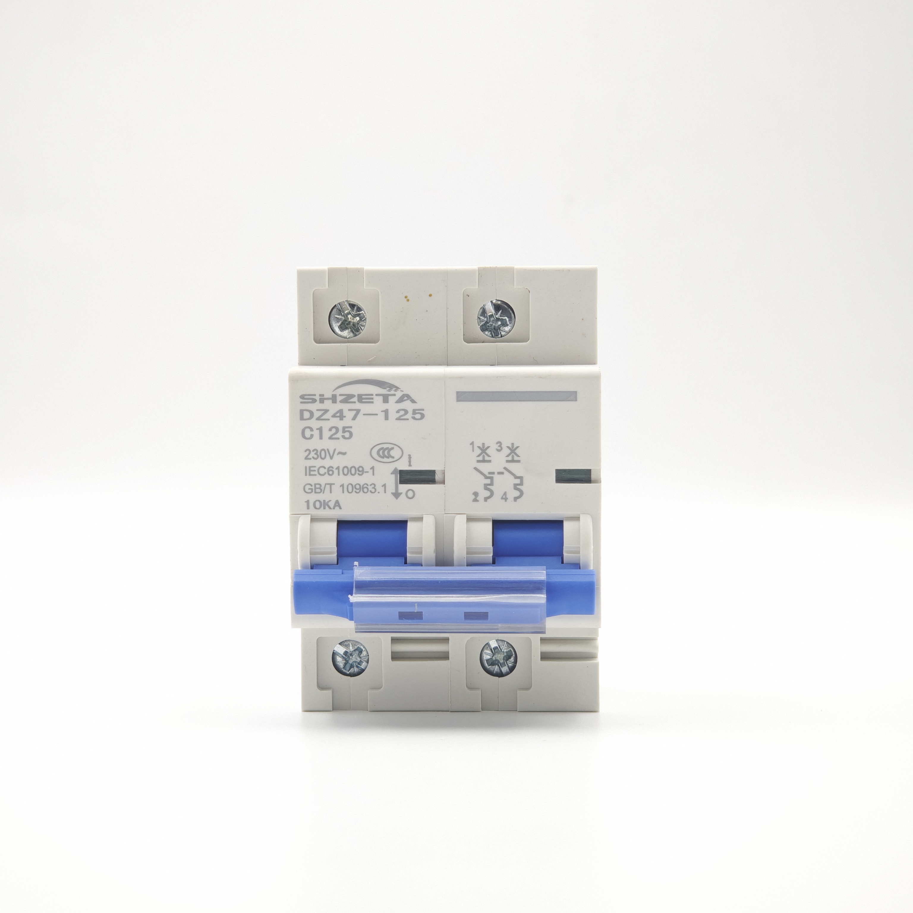
CE Certified DC Circuit Breaker MCB Red Copper Miniature Solar Protection High Efficiency
- Conductor Material: T2 High-Purity Red Copper
- Certification Mark: CE / RoHS Directive
- Arc Quench Chute: 13-Plate De-ion Grid
- Thermal Stability: -35°C to +70°C Ambient
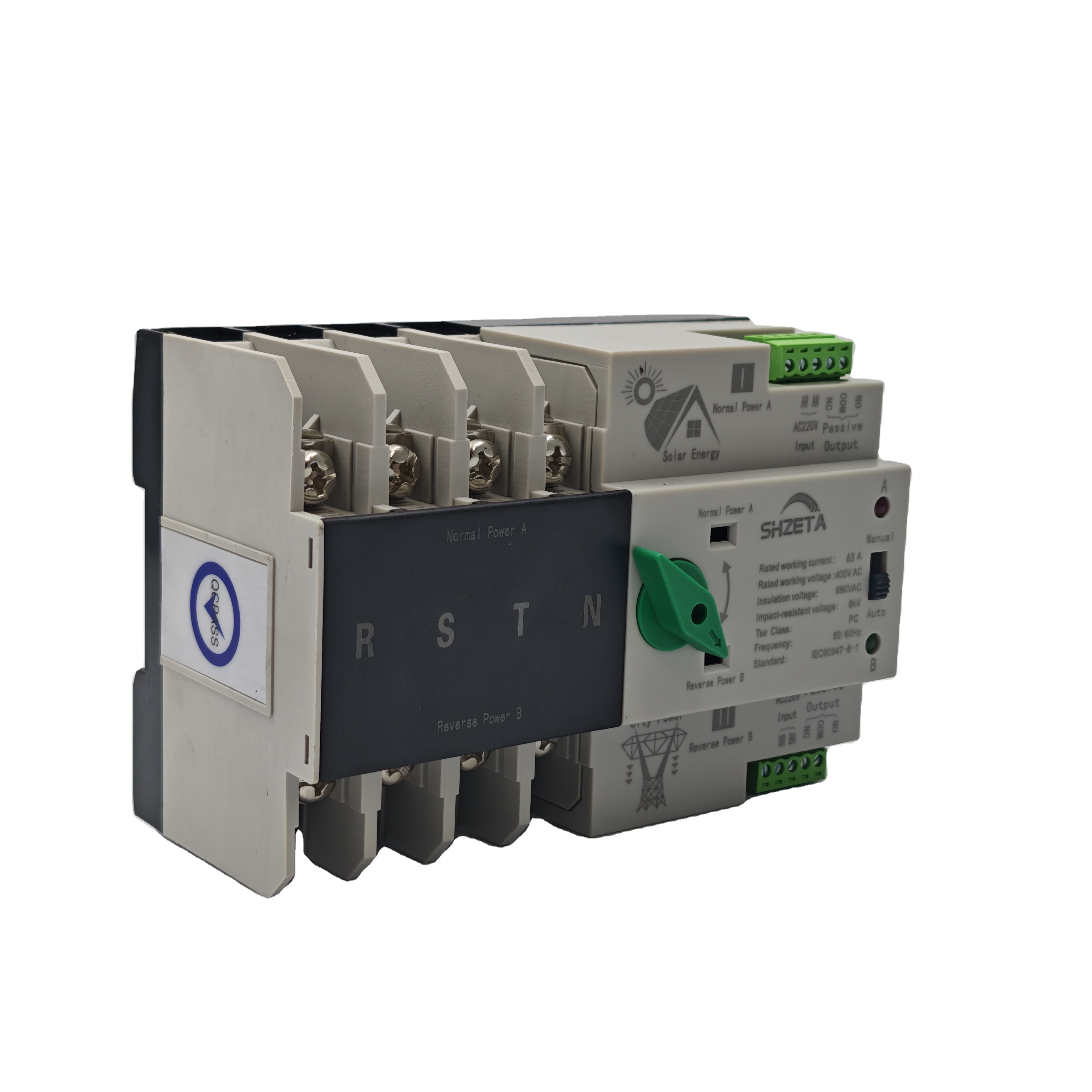
Din Rail ATS Double Power Automatic Transfer Switch 4P 100A 125A Three Phase PC Type AC 400V OEM
- Current Calibration: 100A / 125A Dual Rating
- Controller Integration: Integrated Logic Processor
- Transfer Time: < 30ms Ultra-Fast
- Mounting Design: Standard 35mm Rail DIN
Electro-Mechanical Design & Contact Metallurgy in High-End OEM Power Contactors
In industrial electro-mechanical systems, the power contactor represents the foundational interface between low-level electronic control logic (PLCs, microcontrollers, distributed control systems) and heavy-duty, high-inertia inductive loads. According to IEC 60947-4-1 (Electromechanical Contactors and Motor-Starters), a reliable power contactor must maintain uninterrupted thermal current capacity while withstanding severe locked-rotor transient inrush currents up to 8 to 10 times the rated operational current ($I_e$) during motor start-up sequencing.
As a specialized OEM and ODM manufacturer based in Liushi, Zhejiang, Graybar engineers contactors through finite element analysis (FEA) of magnetic flux paths, optimized electromagnetic coil geometries, and proprietary contact tip metallurgy. Standard generic contactors often utilize sub-optimal silver-nickel ($AgNi$) or low-grade silver-cadmium-oxide alloys ($AgCdO$), which fail to balance anti-welding properties against RoHS environmental compliance directives. Our manufacturing process standardizes on advanced sintered Silver Tin Oxide ($AgSnO_2$) and Silver Indium Oxide ($AgInO_3$) composites. These micro-structured materials exhibit exceptional thermal endurance, superior resistance to arc erosion during severe break cycles, and minimal material migration under continuous direct-current stress profiles.
The arc extinction phase represents the primary vector of contact wear and switchgear degradation. When interrupting an inductive load (Utilization Category AC-3 or AC-4), the magnetic energy stored in the motor windings discharges across the opening air gap, generating a localized plasma column that can exceed 6,000 Kelvin. Our CJX2 and modular power contactor series integrate multi-plate de-ionizing arc chutes constructed of nickel-plated structural steel. The magnetic field induced by the arc current automatically propels the plasma upward into the splitter plates via Lorentz forces, splitting the high-voltage arc into series micro-arcs, cooling the ionized gas, and extinguishing the plasma within milliseconds before contact bounce can initiate destructive re-strikes.
Electromagnetic Core Dynamics
Engineered silicon steel laminations with micro-ground pole faces and pure copper shading rings eliminate mechanical coil hum, reduce eddy current losses, and ensure instantaneous closing force to eliminate contact chatter.
Flame-Retardant Thermoplastics
Housings injection-molded from virgin PA66 reinforced with 30% glass fiber, certified to UL 94 V-0 flame rating and glow-wire test IEC 60695-2-12 up to 960°C, guaranteeing enclosure integrity under flashover conditions.
Multi-Frequency Coil Adaptability
Precision-wound Class H enameled copper wire coils operable across wide voltage envelopes (85% to 110% of rated Us). Compatible with 50Hz, 60Hz, and universal electronically regulated DC driver systems.
OEM Contactor Selection & Operational Envelope
Compare thermal rating classifications, contact architectures, and short-circuit withstand capabilities across our primary industrial power contactor platforms.
| Product Platform | Rated Current ($I_e$ AC-3 380V) | Thermal Current ($I_{th}$) | Standard Control Voltage ($U_s$) | Contact Metallurgy | Electrical Life (Ops) | Mechanical Life (Ops) | Standard Compliance |
|---|---|---|---|---|---|---|---|
| CJX2-09 / 12 | 9A – 12A | 20A – 25A | 24V, 110V, 220V, 380V AC | AgSnO2 (88/12) | 1,000,000 | 10,000,000 | IEC/EN 60947-4-1 |
| CJX2-18 / 25 / 32 | 18A – 32A | 32A – 50A | 24V to 415V AC / DC | AgSnO2 (88/12) | 1,000,000 | 8,000,000 | IEC 60947-4-1, UL 508 |
| CJX2-40 / 50 / 65 | 40A – 65A | 60A – 80A | 110V, 220V, 380V AC | AgSnO2In2O3 | 800,000 | 6,000,000 | IEC/EN 60947-4-1 |
| CJX2-80 / 95 | 80A – 95A | 125A | Wide-band AC/DC Drive | AgSnO2 (90/10) | 600,000 | 6,000,000 | IEC 60947-4-1, GB/T 14048.4 |
| Modular ATS Series | 63A – 125A | 63A – 125A | 220V / 230V AC Single/3-Phase | AgCd-Free Composite | 8,500 Complete Transfers | 15,000 | IEC 60947-6-1 Class PC/CB |
| Solar PV DC Breaker | Up to 125A DC | 125A | Unpowered (Magnetic Trip) | T2 Solid Copper Bridge | 1,500 Full Interruption | 10,000 | IEC 60947-2, CE Certified |
Future Procurement Trends in Industrial Power Contactors & Switching Devices
Strategic procurement of electromechanical components is shifting rapidly away from transactional spot-purchasing toward system-integrated life cycle procurement. As global OEMs, panel builders, and energy engineering EPCs navigate volatile raw material costs (particularly electrolytic copper, pure silver, and magnetic steel) alongside strict regional carbon-accounting frameworks, several fundamental procurement vectors have emerged:
Direct Factory Customization (ODM)
Procurement teams are bypassing intermediary trading tiers to partner directly with authenticated manufacturers capable of tooling private-label housings, laser-etched wiring schematics, and client-tailored auxiliary contact configurations.
Total Cost of Ownership (TCO) Metrics
Evaluations prioritize electrical lifespan ($10^6$ AC-3 switching operations) over baseline piece price. Premature contact welding or high coil holding wattages cause switchboard thermal management penalties and costly field warranty recalls.
Supply Chain Nearshoring & Dual-Sourcing
Industrial conglomerates demand secondary audited manufacturing nodes located in deep component clusters like Liushi, Wenzhou, guaranteeing resilient access to raw copper stamping, coil winding, and plating infrastructure.
Technological Horizons: Wide-Bandgap Integration & Intelligent Switching
The electrification megatrend—driven by commercial Electric Vehicle Supply Equipment (EVSE), Battery Energy Storage Systems (BESS), and distributed Photovoltaic (PV) arrays—is forcing rapid evolution in conventional electromagnetic contactor architecture. Traditional AC contactors are ill-equipped to break bidirectional high-voltage DC circuits where the absence of a natural AC sinusoidal current zero-crossing enables sustained, destructive electric arcs.
1. High-Voltage Direct Current (HVDC) Contactors: The industry is moving from standard 400V AC platforms to hermetically sealed, ceramic-brazed or gas-filled (pure hydrogen or nitrogen pressurized) contactors capable of safely isolating circuits from 500V DC up to 1,500V DC. Permanent NdFeB magnets embedded in the arc chamber create transverse magnetic blowout forces, driving DC arcs outward into ceramic splitters irrespective of current direction.
2. Hybrid Solid-State / Electromechanical Topologies: Pure solid-state relays (SSRs) offer arc-free switching but suffer from inherent forward-conduction voltage drops (dissipating massive heat requiring bulky heat sinks). Next-generation OEM contactors combine silicon-carbide (SiC) MOSFETs or IGBTs in parallel with low-resistance mechanical contacts. The semiconductor conducts exclusively for several microseconds during the opening and closing transitions—eliminating all arc formation—while mechanical silver contacts handle steady-state conduction with zero thermal penalty.
3. Electronic Coils and Predictive Edge Telemetry: Standard copper wire coils dissipate continuous holding power (e.g., 10W to 35W per unit in large frames). Modern developments utilize micro-controlled electronic wide-range coils that apply high initial pull-in current for dynamic closing force, automatically throttling down to a micro-watt pulse-width-modulated (PWM) holding state, cutting power dissipation by up to 80% while tolerating severe network voltage dips without dropping out.
Zhejiang Graybar Electric: Manufacturing Capabilities & OEM Advantages
Combining geographical cluster advantages with rigorous ISO-aligned process controls to deliver world-class low-voltage protection apparatus.
Liushi Hub Advantage
Located in Huangyu Village, Liushi Town, Wenzhou—the undisputed global hub of electrical component production. We command instant access to tier-one raw materials, silver alloy foundries, precision stamped copper, and rapid sea freight logistics via Ningbo and Shanghai ports.
Precision Automated Quality
From automated coil winding and contact rivetting to robotic assembly cells, human error is designed out of critical tolerance chains. Every contactor undergoes 100% automated dielectric withstand tests, contact bounce timing, and pickup/drop-out voltage calibration.
Flexible Low MOQ Scaling
We bridge the gap between prototyping and high-volume deployment. Standard MCB, MCCB, and contactor lines support low initial trial runs (starting from 5 units; ACBs from 1 unit), enabling our partners to validate specifications, fitment, and branding before scale-up.
Comprehensive BOM Sourcing
Eliminate supply chain fragmentation. Source your complete low-voltage distribution architecture from one single audited manufacturer: MCBs, MCCBs, Air Circuit Breakers (ACB), Surge Protective Devices (SPD), Manual/Automatic Transfer Switches (ATS), and AC Contactors.
Frequently Asked Questions for Electrical Engineers & Sourcing Managers
Comprehensive engineering guidance addressing contactor selection, utilization categories, coordination standards, and customization capabilities.
What is the fundamental engineering difference between AC-1 and AC-3 contactor ratings?
The difference lies in load power factor, inrush current characteristics, and operational severity defined by IEC 60947-4-1. Utilization category AC-1 applies to non-inductive or slightly inductive loads, such as resistive resistance heating furnaces and general distribution circuits, where power factor ($\cos \phi$) is $\ge 0.95$. In AC-1, breaking current equals rated operating current ($I_c = I_e$). Conversely, AC-3 covers squirrel-cage induction motors where interruption occurs while the motor runs at rated speed. Here, the contactor must make inrush currents of $5 \times$ to $8 \times I_e$ and break full load current at $\cos \phi \approx 0.35$. Consequently, an identical physical contactor frame might carry a 32A rating under AC-1 conditions, but be derated to 18A or 12A under AC-3 conditions to ensure electrical contact lifespan.
How does Type 1 short-circuit coordination differ from Type 2 coordination for motor starter combinations?
Under IEC 60947-4-1, coordination describes the interaction between an upstream short-circuit protective device (SCPD, such as an MCCB or backup fuse) and a contactor/overload relay assembly during high fault currents. Type 1 Coordination requires that under a short-circuit fault, the equipment causes no danger to persons or installation; however, the contactor and overload relay are allowed to suffer permanent internal damage, contact destruction, or welded contacts, requiring repair or complete replacement before restarting. Type 2 Coordination mandates that under short-circuit conditions, no damage occurs to the contactor or overload relay, and the assembly must be capable of immediate further service. Light contact tack-welding is permitted only if it can be easily separated with a standard screwdriver without replacement of components. Type 2 designs require precise engineering of contact mass, contact spring force, and blow-open threshold coordination with the protective breaker.
Why is silver tin oxide (AgSnO2) preferred over silver cadmium oxide (AgCdO) in our custom OEM contact points?
Historically, Silver Cadmium Oxide ($AgCdO$) was the industrial benchmark due to its balanced resistance to arc erosion and contact welding. However, Cadmium is a heavy metal classified as hazardous under European Union RoHS directives (Directive 2011/65/EU and 2015/863). Our factory transitioned early to advanced sintered Silver Tin Oxide ($AgSnO_2$) and $AgSnO_2In_2O_3$ formulations. Metallurgically, $AgSnO_2$ offers a significantly higher thermodynamic decomposition temperature, making it far superior in withstanding high locked-rotor peak inrushes and motor jogging duties (AC-4) without contact welding. It demonstrates lower overall arc-erosion mass loss, zero toxic vapor outgassing during catastrophic short-circuit flashover, and guaranteed legal compliance across European, North American, and East Asian regulatory jurisdictions.
Can standard AC contactors be repurposed for direct current (DC) load breaking applications?
Using standard AC contactors in DC circuits without specific engineering modifications or substantial derating creates serious operational risks. Alternating current naturally passes through zero volts 100 or 120 times per second (in 50/60Hz systems), which assists the arc chute in extinguishing the plasma. Direct current provides continuous, constant voltage with no natural zero-crossing. If an unadapted AC contactor attempts to break high-voltage DC (e.g., above 48V DC), the arc will persist inside the housing, rapidly melting the carrier plastic, welding contacts, or triggering a line-to-line phase-to-ground flashover explosion. When using standard 3-pole or 4-pole contactors for DC applications, poles must be wired in series to divide the DC arc voltage across multiple air gaps, and the unit must be selected according to Utilization Categories DC-1, DC-3, or DC-5, or customized at our factory with embedded permanent magnetic blowouts.
What causes electromagnetic contactor buzzing (coil hum) and how does Graybar eliminate it?
Contactor coil hum or acoustic buzzing in AC electromagnetic systems originates from the cyclical magnetic flux fluctuation crossing zero at double the line frequency. When magnetic force momentarily falls below the mechanical reaction spring counter-force, the armature experiences microscopic physical vibrations against the yoke pole faces. To counteract this, Graybar embeds precision-stamped, highly conductive copper shading rings into the outer lamination faces of the stationary E-core. The shading ring creates a phase-shifted secondary magnetic flux that maintains mechanical hold during the main current zero-crossing. Furthermore, our automated CNC grinding line machines core pole faces to optical flatness tolerances, preventing air gap misalignments caused by dust ingress, protective oil residues, or uneven mechanical seating.
What coil surge suppression technologies are available for PLC direct-drive applications?
When an electromagnetic coil is de-energized, its collapsing magnetic field generates a massive inductive counter-electromotive force (CEMF) back-EMF spike that can exceed 1,500V to 3,000V with high $dv/dt$ slew rates. This voltage transient can puncture coil insulation, destroy connected solid-state PLC transistor outputs, or emit severe high-frequency electromagnetic interference (EMI) that resets microprocessor controls. Graybar provides three OEM surge suppressor module configurations designed to clip directly onto the contactor housing: RC Snubber Networks (ideal for AC coils, absorbing transients without extending release drop-out times), Metal Oxide Varistors (MOV) (clamping overvoltages at roughly $2 \times U_n$, compatible with both AC and DC controls), and Flyback Diodes / Zener Clamps (for DC coils, delivering absolute peak voltage suppression, though slightly lengthening mechanical drop-out times).
How should power contactors be derated when operating at high ambient temperatures or high altitudes?
Standard operational data sheets assume ambient air temperatures of $\le 40^\circ\text{C}$ and installation altitudes under 2,000 meters above sea level. In enclosed motor control centers or tropical installations where ambient internal cabinet temperature reaches $60^\circ\text{C}$, thermal dissipation from current-carrying conductors degrades; current capacity must be derated by a factor of approximately 0.82 to 0.88, or upgraded to the next physical frame size. Above 2,000 meters, lower atmospheric pressure reduces both dielectric breakdown strength of the air gap and convective cooling capacity. At 3,000 meters, rated operational voltage ($U_e$) must be derated to 85% and operational current ($I_e$) to 92%. At 4,000 meters, dielectric ratings require derating to 75% and current to 82%.
What level of custom private-label branding and mechanical packaging do you provide for OEM distributors?
We operate comprehensive OEM and ODM programs. Customization includes fiber laser marking of customer brand logos, trademark designations, and customized single-line connection schematics directly onto the front housing. We offer tailored molding options for plastic faceplate colors, terminal screw configurations (Phillips, Pozidriv, or slotted hex-head combined clamp screws), and custom auxiliary configuration modules (1NO+1NC, 2NO+2NC, pneumatic timers, or side-mount aux units). For retail and wholesale distributors, we engineer client-branded full-color packaging boxes, multilingual instruction manuals, barcode labeling, and heavy-duty moisture-sealed master export cartons tailored for international ocean transit.
What is the difference between a PC-Class ATS and a CB-Class ATS in dual-power systems?
Under IEC 60947-6-1, automatic transfer switching equipment is categorized into classes based on internal construction and overcurrent handling capability. A PC-Class ATS utilizes specialized contactor or load-break switch mechanisms that are capable of making and withstanding short-circuit currents, but do not provide internal thermal and magnetic overcurrent trip units; it is engineered for maximum reliability, compact footprint, fast transfer times (<50ms), and relies on dedicated upstream circuit breakers or fuses for overcurrent clearance. A CB-Class ATS is constructed using two mechanically and electrically interlocked circuit breakers equipped with integrated overcurrent trip mechanisms. If a short circuit occurs downstream, a CB-class unit will trip independently to clear the fault.
What quality testing and factory acceptance procedures are carried out on production batches?
Every production run at our Liushi facility undergoes strict multi-tier quality assurance. Incoming inspection verifies silver tip brazing thickness via ultrasonic acoustic testing and spectrometer alloy analysis. During assembly, coil resistance and insulation integrity are checked. 100% of finished units pass through our automated End-of-Line (EOL) functional stations, which perform: 1) Dielectric withstand tests at 2,500V AC for 1 minute; 2) Pick-up voltage verification (ensuring reliable engagement at 85% of rated $U_s$ under cold coil conditions) and drop-out voltage verification (ensuring clean drop-out between 20% and 75% of $U_s$); 3) High-speed optical sensor measurement of contact bounce timing (holding contact chatter below 2.5 milliseconds to eliminate initial contact erosion); 4) Dynamic contact resistance measurement (<1.5 milliohms per pole).
Accelerate Your Switchgear & Contactor Procurement
Connect directly with our application engineering team in Liushi, Wenzhou. Request comprehensive product specification binders, CAD models, single-line compatibility reviews, or arrange sample evaluation units for your engineering laboratory.