EN/IEC 60947-6-1 Certified Engineering

CE Certified Dual Power Transfer Switch Manufacturers & Factories

Global B2B procurement intelligence, class-PC and class-CB switchgear architecture, OEM customization specs, and factory verification from Liushi, Wenzhou.

Factory Direct Equipment

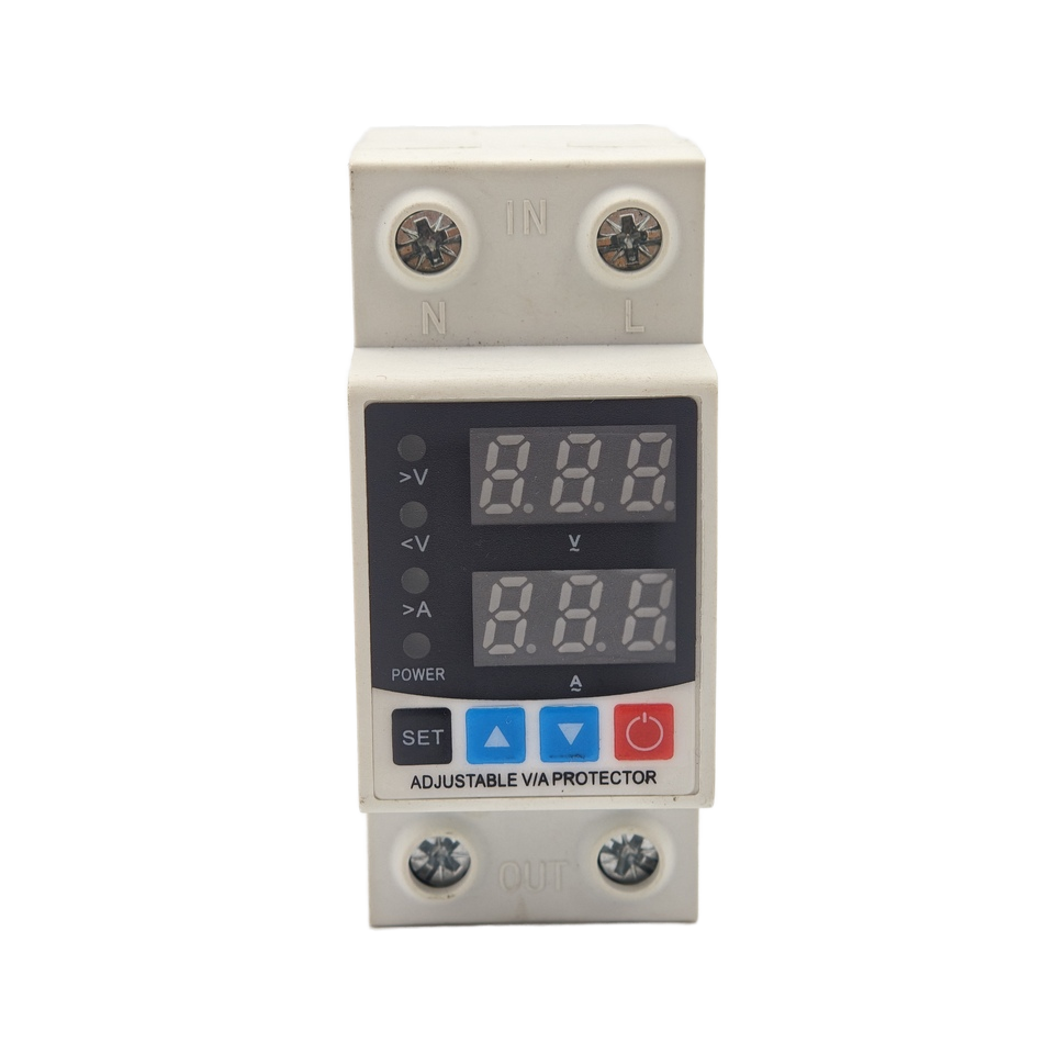
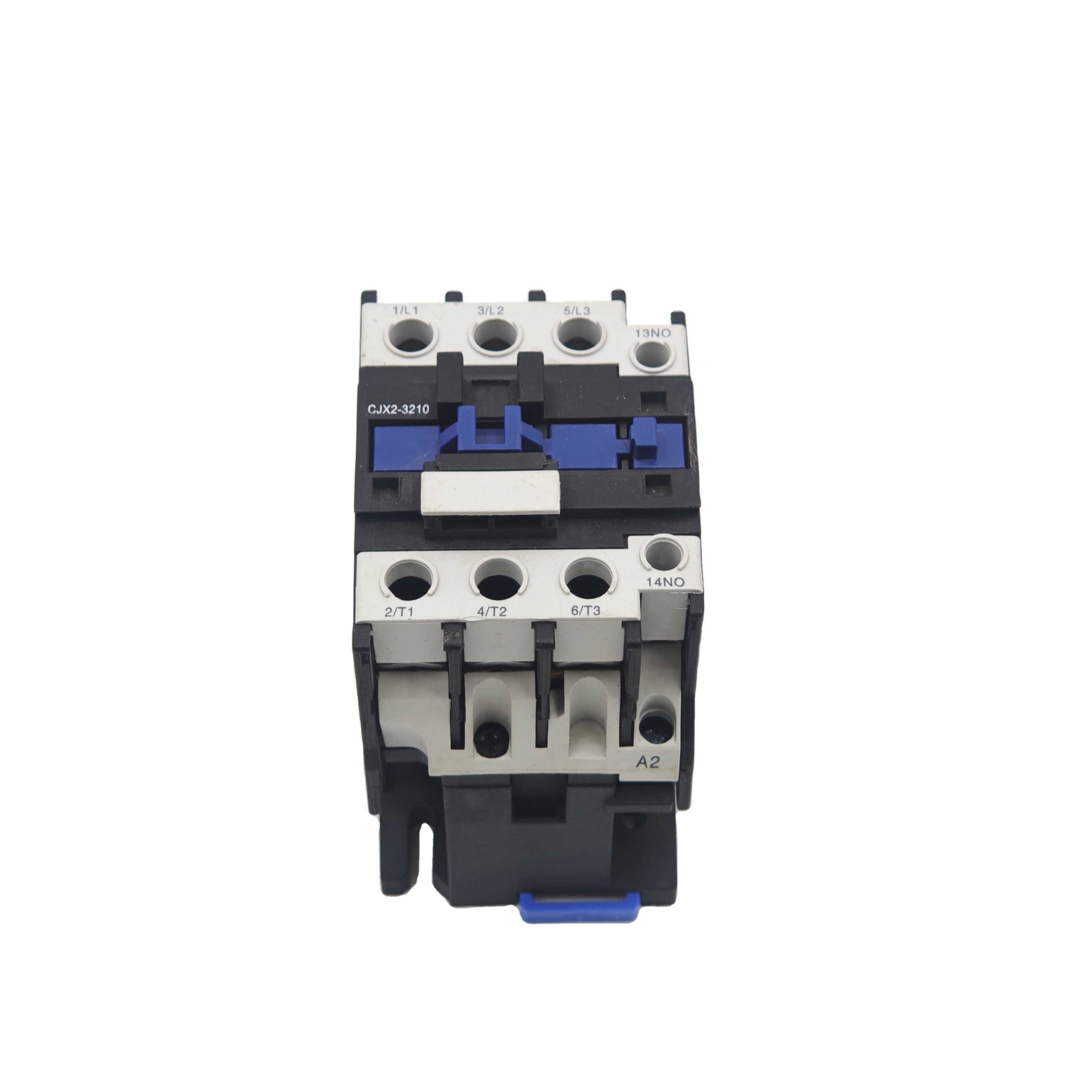
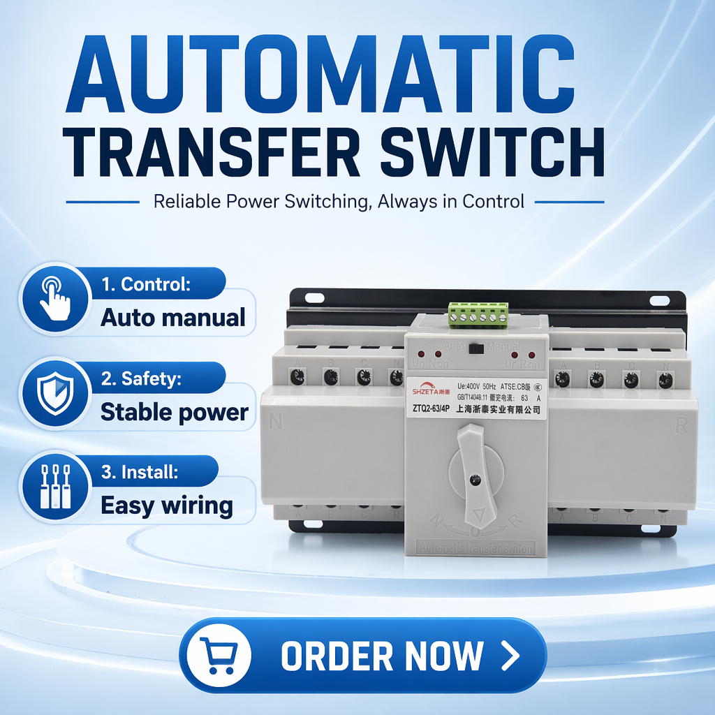
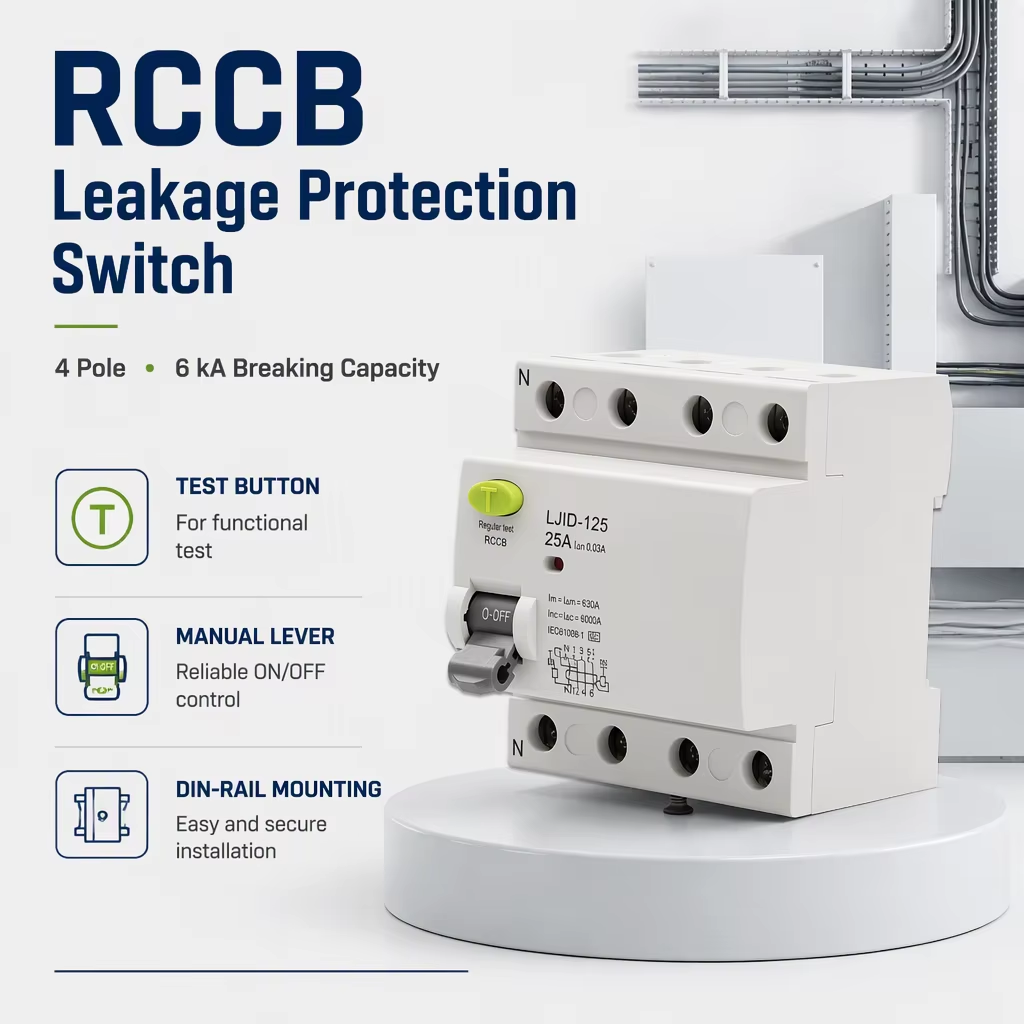
Featured Low-Voltage Protection & Transfer Switches

Examine our certified production range. Built to stringent international endurance standards, each unit delivers robust breaking capacity, arc-quenching dynamics, and seamless automatic switching for mission-critical power architectures.
5pcs

Ultra-Low Sample Order Threshold

<50ms

PC-Class Transfer Interruption Time

8kA

Max Short-Circuit Making Capacity (Icm)

100%

Dielectric & Mechanical QA Verified

Engineering Whitepaper

The Definitive Engineering Guide to CE Certified Dual Power Transfer Switches (ATS)

In modern industrial facilities, data centers, tier-3 healthcare networks, and distributed renewable microgrids, continuous power supply is not merely a convenience—it is a life-safety requirement and a business-critical parameter. A Dual Power Automatic Transfer Switch (ATS) acts as the primary mechanical and electrical junction that switches mission-critical electrical loads between a preferred utility grid source and an alternative reserve source (such as a standby diesel generator, photovoltaic solar array, or battery energy storage system). Achieving official European Conformity (CE) marking requires rigorous compliance with the Low Voltage Directive (LVD 2014/35/EU), the Electromagnetic Compatibility Directive (EMC 2014/30/EU), and strict alignment with the standard EN / IEC 60947-6-1: Low-voltage switchgear and controlgear – Multiple function equipment – Transfer switching equipment (TSE).

1. PC-Class vs. CB-Class Transfer Switches: Critical System Coordination

A frequent error among procurement managers and switchgear panel builders is treating all transfer switches as interchangeable assemblies. International engineering standards clearly delineate between two fundamental architectures:

  • PC-Class Transfer Switching Equipment (TSE): Designed with a dedicated electromagnetic drive or motor-driven solenoid mechanism capable of making, carrying, and interrupting normal operational load currents. Crucially, a PC-class switch possesses a certified rated short-time withstand current (Icw) and short-circuit making capacity (Icm), but it does not incorporate integral thermal-magnetic overcurrent trips. It depends upon upstream circuit protection devices (MCCBs or fuses) to interrupt short circuits. Because of their lack of built-in tripping components, PC-class transfer switches exhibit exceptional contact reliability, zero trip false-positives under transient surges, and transfer speeds commonly under 50 milliseconds.
  • CB-Class Transfer Switching Equipment (TSE): Built by mechanically interlocking two conventional circuit breakers (typically Molded Case Circuit Breakers - MCCBs, or Miniature Circuit Breakers - MCBs) equipped with integral overcurrent release mechanisms. In a CB-class setup, if a high downstream fault current occurs, the internal breaker can trip independently. However, if the secondary source breaker also trips upon closing into a fault, downstream loads remain unpowered until a manual physical reset is executed. CB-class switches are cost-effective for general commercial facilities where dedicated downstream feeder protection is absent.

Electromagnetic Coil Drive

Our PC-class switch units utilize an instantaneous solenoid impulse drive that consumes power only during the transition cycle. This eliminates continuous coil hum, minimizes parasitic load, and yields an ultra-fast changeover sequence (<30ms operating cycle).

Dual Mechanical & Electrical Interlocking

To eliminate any prospective cross-connection between unsynchronized utility grids and backup generator phases, our switches incorporate hardened rotary interlock cams supplemented by electrical coil cross-tripping circuits, ensuring zero backfeeding.

Silver-Tin-Oxide (AgSnO2) Contacts

Main switching contact bridges are cold-riveted using premium AgSnO2 alloy plates. This metallurgical composition delivers outstanding anti-welding properties during short-circuit withstand events and curbs contact erosion caused by AC-33B inductive arcing.

2. Electrical Ratings Comparison: PC-Class vs. CB-Class vs. STS

To guide EPC contractors, panel builders, and plant electrical directors in specifying the optimal device for power resilience, review the empirical comparison matrix below:

Switchgear Topology Standard Reference Transfer Duration Overload Duty Cycle Short-Circuit Handling Maintenance Lifecycle
PC-Class Solenoid ATS EN 60947-6-1 20ms – 50ms AC-33B (Frequent Inductive Switching) High Withstand (Icw up to 10kA / 1s) 10,000+ Mechanical Cycles (No Trip Calibrations)
CB-Class MCCB ATS EN 60947-2 / 6-1 80ms – 250ms AC-31B (Non-Inductive or Low Inductive) Integral Trip Release (Icu Rated) 4,000 – 6,000 Cycles (Periodic Trip Testing Required)
Contactor-Based ATS EN 60947-4-1 50ms – 100ms AC-1 / AC-3 Operations Moderate; Requires Fast Current Limiting Backup High Mechanical Life, Continuous Coil Draw
Static Transfer Switch (STS) EN 62310-1 < 5ms (Sub-Cycle) Sensitive Electronics / Data Centers SCR Thyristors; Sensitive to High Fault Currents No Moving Parts; Requires Active Cooling / High CapEx

3. Future Sourcing & Procurement Trends (2025–2030)

As the international power grid decentralizes under rapid adoption of renewable distributed energy resources (DERs), dual power transfer switches are evolving beyond basic changeover hardware. Forward-looking procurement strategies must account for these dominant engineering transitions:

  • Hybrid Renewable-Storage Microgrid Topologies: Modern commercial architectures no longer switch solely between coal-fired grid lines and diesel gen-sets. Procurement is shifting towards multi-source ATS units capable of coordinating between Utility Mains, Solar Inverters, and Battery Energy Storage Systems (BESS). Dual-power transfer switches now feature fire-fighting linkage (tripping to position "0" under fault conditions) and smart signal outputs for inverter synchronization.
  • Embedded Edge Telemetry and Modbus-RTU/BACnet Integration: Legacy dry contacts are rapidly being replaced by microprocessor-driven smart controllers. Procurement tenders increasingly dictate on-board RS485 interfaces delivering real-time RMS phase voltage, system frequency, active power factor, and switch position reporting directly into central building SCADA platforms.
  • Decoupled Neutral Switching in 4-Pole (4P) Configurations: The proliferation of switch-mode power supplies, variable frequency drives (VFDs), and nonlinear IT equipment causes elevated triplen harmonic currents (3rd, 9th, 15th harmonics) in the neutral conductor. Specifying true 4-pole dual power transfer switches prevents circulating earth currents, eliminates false tripping of upstream residual current devices (RCCB/RCDs), and guarantees compliance with European TT and TN-S earthing protocols.
Direct From The Manufacturing Hub

Why Global Buyers Partner With Zhejiang Graybar

Headquartered in Liushi Town, Wenzhou—China's global capital for low-voltage electrical apparatus—Zhejiang Graybar Electric Co., Ltd. combines upstream supply chain agility with rigorous international manufacturing practices.

Precision Engineering & Low-Voltage Manufacturing Scalability

Whether you require standard 63A PC-Class transfer switches for telecom towers or custom 630A MCCB-based ATS units for industrial distribution assemblies, Graybar manages the entire manufacturing cycle under one roof: injection molding of flammability V0 housings, contact bridge riveting, microprocessor programming, and automated end-of-line verification.
  • ✓
    Liushi Industrial Ecosystem: Unmatched raw material localization (high-purity electrolytic copper, AgCdO/AgSnO2 contact tips, custom bimetal elements) guarantees rapid production scaling and uncompromised cost efficiency.
  • ✓
    Comprehensive IEC/EN Test Laboratory: Every switch batch undergoes strict dielectric withstand testing (2.5kV AC / 1 min), contact resistance measurement, and multi-cycle operational testing under full simulated inductive loads before packing.
  • ✓
    Flexible Order Staging (MOQ 5 pcs): We support engineering prototypes, regional distributors, and panel builder testing by offering low minimum order quantities, scaling up seamlessly to high-cube container exports.
  • ✓
    Tailored OEM / ODM Customization: Custom silk-screened private labeling, laser-etched operational schematics, customized auxiliary contact configurations, and multilingual instruction manuals tailored to your target markets.
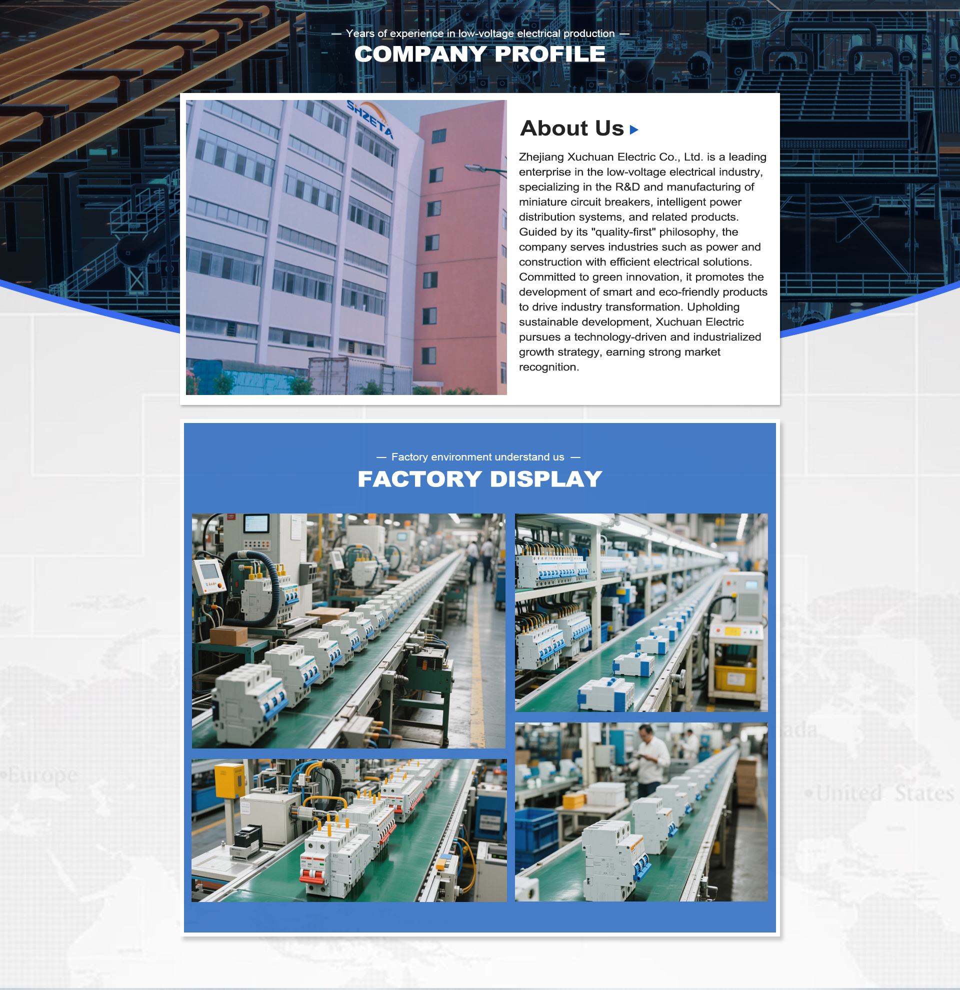
Zhejiang Graybar Electric Factory Facility and Production Hub
Engineering Insights

Frequently Asked Technical Questions (FAQ)

Detailed answers to critical engineering, installation, and procurement queries received by our application engineering department.

What are the key technical criteria for CE certification on a Dual Power Transfer Switch?
To carry the CE mark legally within the European Economic Area (EEA), a Dual Power Transfer Switch must comply with the Low Voltage Directive (LVD 2014/35/EU) and the Electromagnetic Compatibility Directive (EMC 2014/30/EU). The recognized harmonized test standard is EN / IEC 60947-6-1. Verification requires type-testing documentation covering temperature rise limits under continuous rated current, dielectric properties ($U_i = 800\text{V}$, $U_{imp} = 8\text{kV}$), short-circuit making and withstand capacities, operational performance under AC-31B/AC-33B duty cycles, and immunity to radiated/conducted electromagnetic disturbances for electronic control units.
When should I specify a 4-Pole (4P) ATS over a 3-Pole (3P) switch?
A 4-Pole ATS is mandatory in electrical installations utilizing separate earthing systems between the mains and standby sources (e.g., standard TT or TN-S grounding where the generator neutral is independently grounded). If a 3-pole switch with an unbroken neutral is used, stray neutral currents can circulate back into the alternate supply earth, causing improper functioning or nuisance tripping of upstream Residual Current Circuit Breakers (RCCBs). Furthermore, for systems powering nonlinear loads that generate excessive 3rd harmonic neutral currents, a true 4-pole switch isolates phases and neutral completely, preventing potential differences during line changeovers.
What is the difference between open transition and closed transition transfer?
Open Transition ("Break-Before-Make"): The switch completely disconnects the load from the primary source before connecting it to the secondary source. There is a momentary interruption in electrical supply (ranging from 30ms to several seconds depending on mechanical configuration). This is the most common, cost-effective ATS topology and carries no risk of paralleling unsynchronized sources.

Closed Transition ("Make-Before-Break"): The switch synchronizes both sources in phase, voltage, and frequency, momentarily paralleling both paths (typically <100ms) to transfer load without interrupting supply. Closed transition requires utility approval, sophisticated synch-check relays, and strict protection settings to prevent back-energizing utility lines during a grid fault.
How does the short-time withstand current (Icw) impact switch survival?
The rated short-time withstand current ($I_{cw}$) defines the RMS current level that a transfer switch can withstand in the closed state for a specified duration (typically 0.1s, 0.5s, or 1.0s) without suffering thermal or mechanical damage (such as contact welding, conductor distortion, or housing rupture). In systems with high prospective fault levels, upstream protection devices take several cycles to clear the fault. The transfer switch must remain intact during this short interval. A high $I_{cw}$ rating ensures system coordination and reliability in critical industrial installations.
What are the minimum order quantities (MOQ) and lead times for OEM private labeling?
Standard Graybar-branded transfer switches and circuit breakers carry a minimum order quantity of only 5 pieces for evaluation and prototyping. For customized OEM private labeling (including custom front fascias, laser-engraved customer part numbers, custom packaging, and localized user guides), the typical MOQ starts from 50 to 100 units depending on the frame size. Standard order lead times range from 15 to 25 business days from drawing sign-off to port loading in Ningbo or Shanghai.
Can Graybar dual power transfer switches be used with renewable solar and energy storage systems?
Yes. Our PC-class ATS units are widely integrated into off-grid and grid-interactive hybrid solar installations. They manage source changeovers between an AC-coupled hybrid inverter (or battery bank) and the municipal grid. The ultra-fast transition time (under 50ms) ensures that heavy appliances remain operating without triggering inverter inverter over-current lockouts, while auxiliary contacts provide control signals to shed discretionary loads during battery backup operation.
What utilization category should I choose: AC-31B, AC-32A, or AC-33B?
Utilization categories defined in IEC 60947-6-1 specify the electrical switching duty:
  • AC-31A / AC-31B: Non-inductive or slightly inductive loads (heating elements, resistive lighting).
  • AC-32A / AC-32B: Mixed resistive and inductive loads, including small air conditioning and fan groups.
  • AC-33A / AC-33B: Highly inductive loads with frequent motor starting, locked rotor stall conditions, and high inrush transformers. For heavy commercial panels and industrial motor control centers, specifying AC-33B is essential to guarantee adequate contact metallurgy and arc chamber design.
How does the mechanical interlock mechanism prevent cross-phase short circuits?
Graybar ATS units feature a dual safety matrix: First, an internal mechanical interlock lever physically blocks the closing path of Source B whenever Source A is engaged (and vice versa), making simultaneous mechanical closure physically impossible even under severe shock or vibration. Second, an electrical interlock circuit routes the operating coil control lines through auxiliary dry contacts of the opposing switch mechanism. Even if an errant electronic control signal fires simultaneously to both coils, only the de-energized path can actuate.

Accelerate Your Switchgear Supply Chain Today

Connect directly with our application engineering group in Liushi, Wenzhou. Request detailed IEC/CE compliance dossiers, full CAD/BIM models, custom project pricing, and rapid sample staging for your upcoming distribution panel builds.

Get a Quote